

 |
The communication protocol Basically each probe implement functions that can fall in two categories : “get” features and “set” features. The term “feature” identifies a very generic physical quantity. Get features are counters or physical quantities that are sampled by the probe (e.g. temperature, humidity, voltage, etc...) and returned to the controller through the bus protocol, whenever polled by the controller as its discretion. Set features are properties or commands that are sent by the controller to the probe, which will cause actions to be performed by the controller (e.g. switch on a relay, setting a PWM driver frequency, etc...). A set feature is always read and write (it can be useful to get the current status), while a get feature is meant to always be read only. Given the wide variety of fields of use, Probes have been planned with a very generic, easy to expand architecture. This allows new probes to be easily implemented. In order to deploy a very easy-to-expand solution, features and physical ports are in a one to many relation meaning that a probe’s port (or interface) can provide one or more features to the controller. Every feature is assigned three properties, which purpose is to characterize it uniquely within the probe:
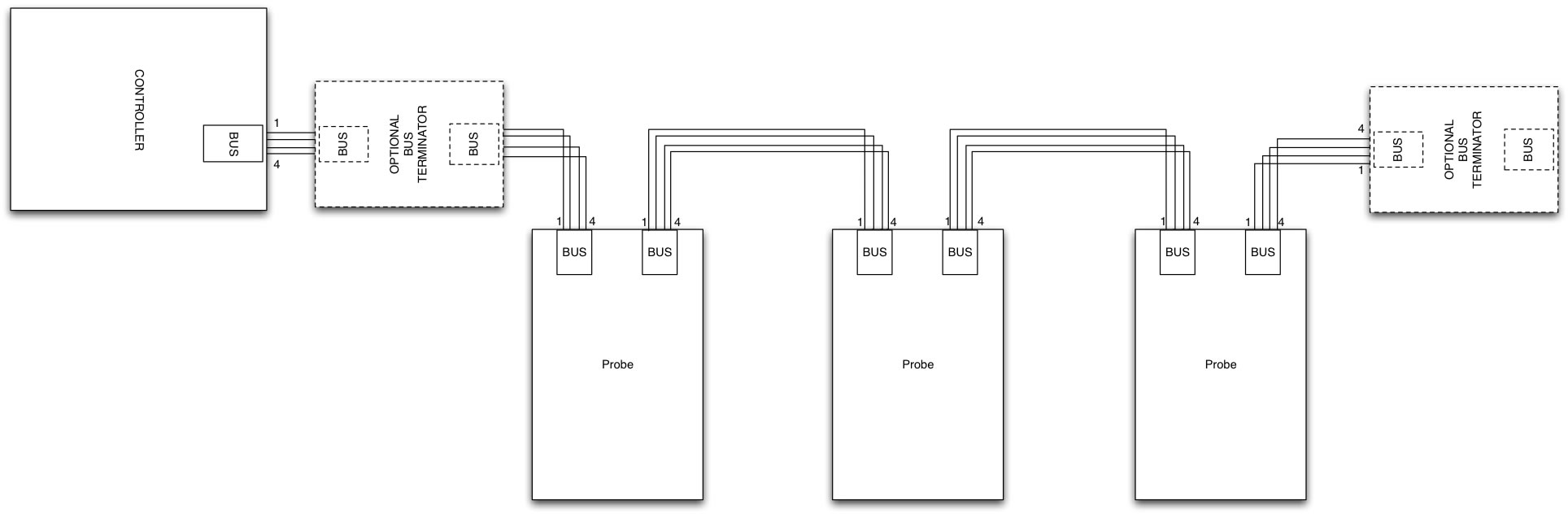
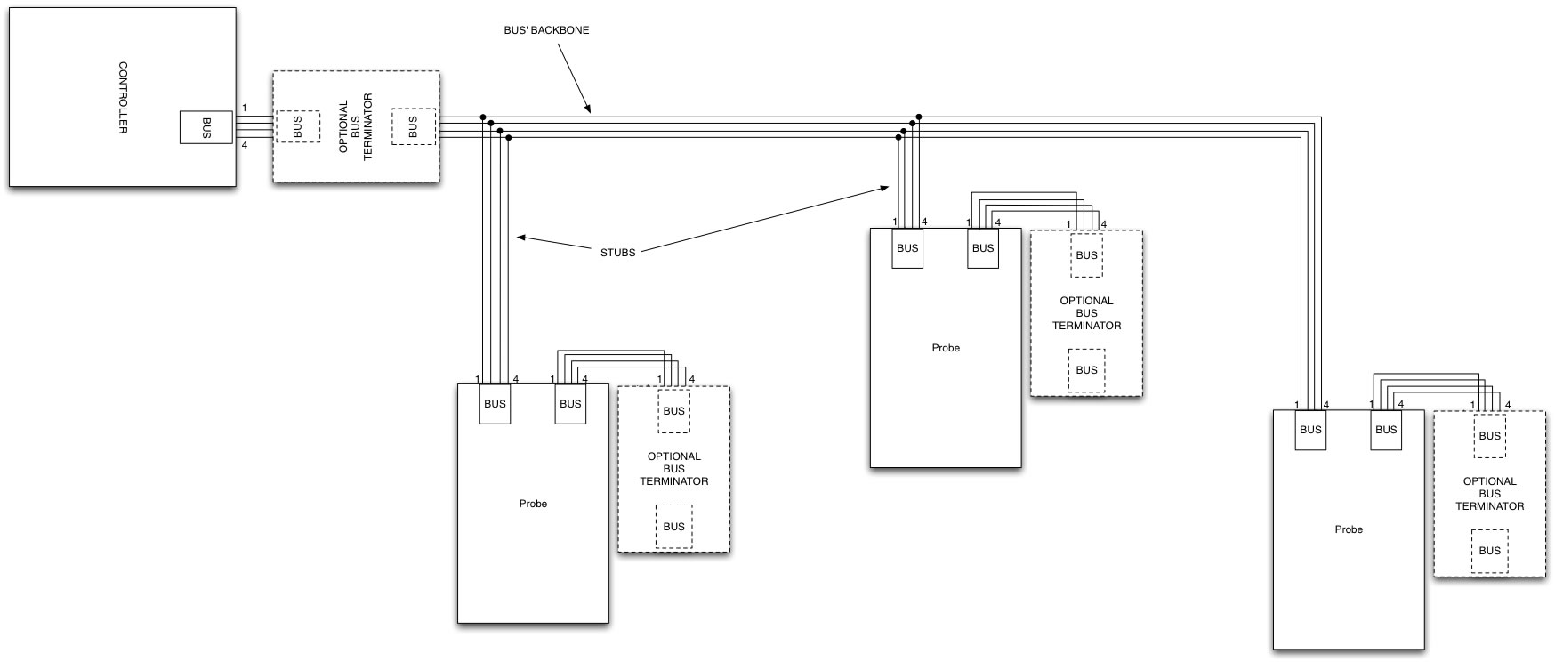
Cabling all together
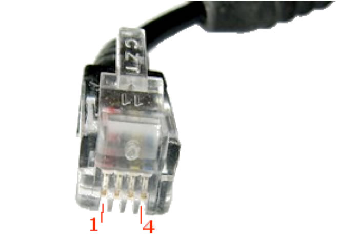
Wiring pinout is the following: 1. 5.0 VDC Power Supply Wiring pinout must be respected throughout all the bus’ length, no crossing must be made. Different kind of probes can be easily connected to the same bus using the supplied bus cable: a straight UTP with RJ9 connectors on both ends. If using custom cables the suggested cable impedance range is 100-600Ω, preferred 120Ω. In order to grant a correct bus setup two topologies are strongly advised: daisy chain (the preferred topology) and bus with short stubs. The maximum stub length depends on the bus speed and the signal propagation speed within the cable, as a rule of the thumb is advised to keep it below 11mt (38ft). Other topologies might be used (such as star ones), but performance would be very likely affected from reflections. Cable termination on its characteristic impedance, whatever the chosen topology, is always advised in order to minimize reflections. Both bus and the communication protocol support multi-master setup, this means more than one controller (which acts as master) can be put in place on the same wires. The number of probes that can be connected on the bus simultaneously, without power supply regenerators or hubs, is function of the following variables:
In order to properly size the number of devices, plan the bus cabling and the power supply, please refer to the devices specifications.
Daisy chain bus topology
Bus with short stubs topology |
 |